KnowledgeECONOMICS
CONTACT US
Hunan Perfect Industry Co.,Ltd
Contact: Manager Hu, Manager Yi
Hotline:008618507312158
Cell phone:008613974960765
Address:Xiangyin County Industrial Park, Yueyang City, Hunan Province, China
Current location: HOME »Knowledge »vertical turbine pump
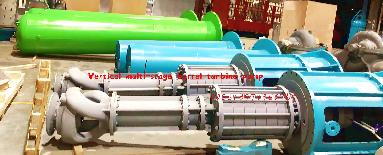
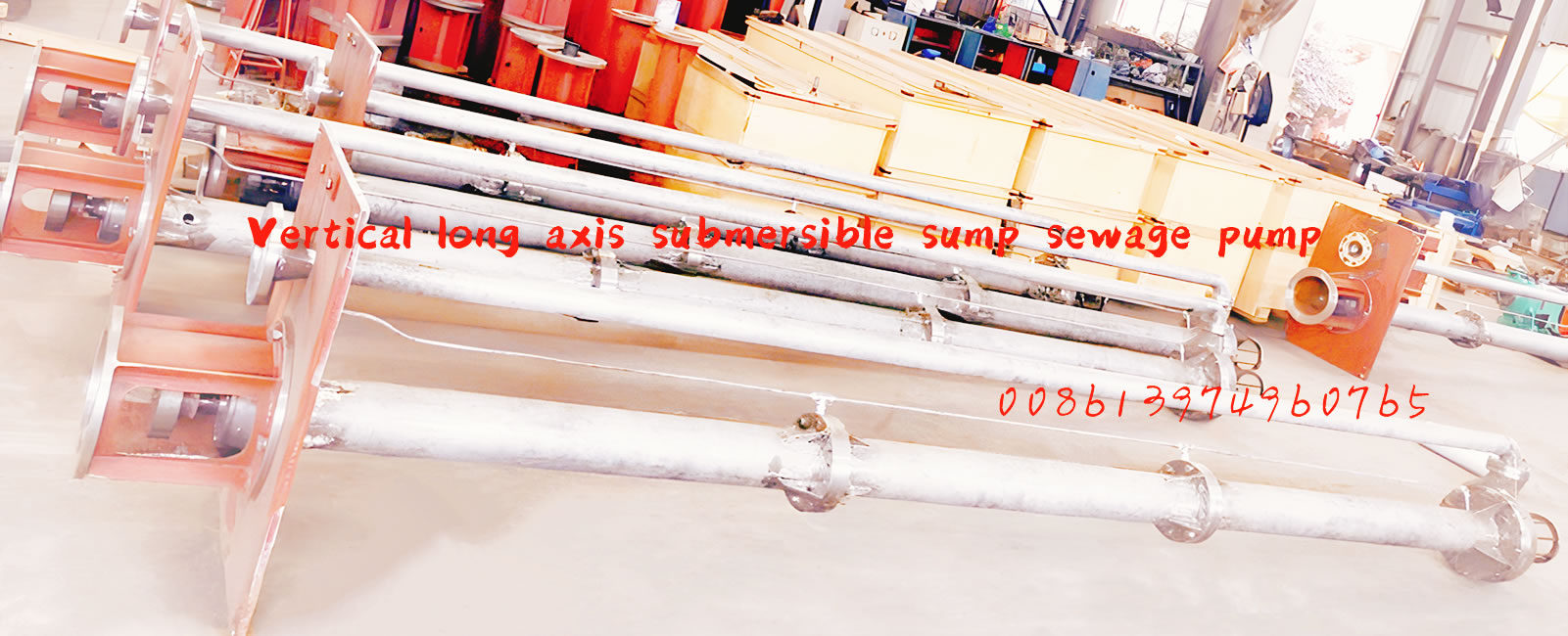
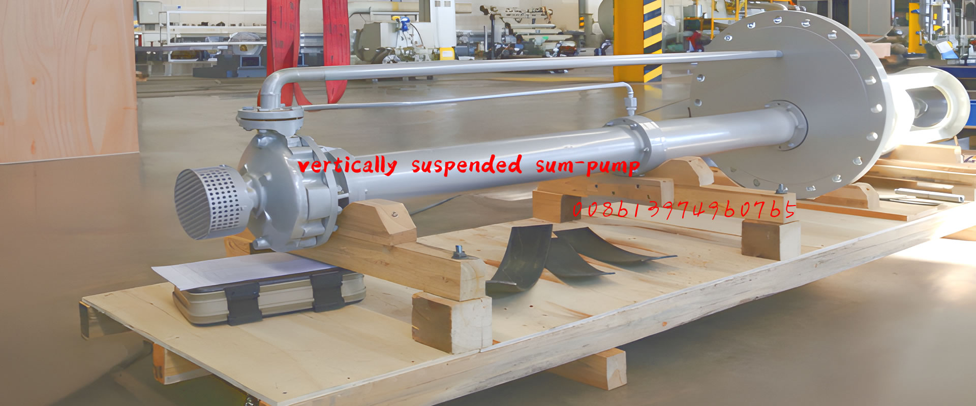
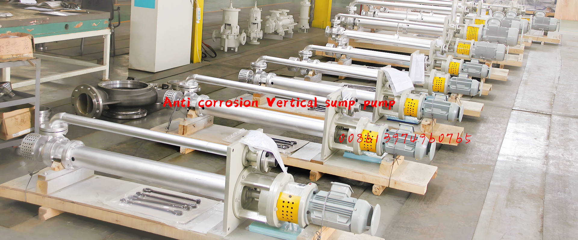
The rust resistant impeller hub structure widely used in vertical inclined flow pumps, vertical suspended semi submersible vertical turbine pumps, and vertical volute pumps
A rust resistant impeller hub structure, comprising an impeller (1), an impeller head (2), and a impeller shaft (7), wherein a first sealing gasket (4) is placed between the lower end surface of the impeller (1) hub and the joint surface of the impeller head (2), a sealing ring (3) is provided on the upper end surface of the impeller (1) hub, and a second sealing gasket (5) is placed between the joint surface of the sealing ring (3) and the sealing ring (3), and an O-ring (6) is installed between the joint surface of the sealing ring (3) and the impeller shaft (7). This technology method has a compact structure and is easy to use. It is widely used in vertical inclined flow pumps, vertical suspended semi submersible vertical turbine pumps, and vertical volute pumps, and has strong practical and promotional value.

Technical requirements: A rust resistant impeller hub structure comprising an impeller (1), an impeller head (2), and an impeller shaft (7), characterized in that a first sealing gasket (4) is placed between the lower end surface of the impeller (1) hub and the joint surface of the impeller head (2), a sealing ring (3) is placed on the upper end surface of the impeller (1) hub, and a second sealing gasket (5) is placed between the joint surface of the sealing ring (3) and the impeller shaft (7), and an O-ring (6) is placed between the joint surface of the sealing ring (3) and the impeller shaft (7).

